Warning
I am not a mechanic or a representative of any motorcycle or tool manufacturer or anything else official. This page is only my notes on doing this procedure myself. Although I believe what I have documented here is correct, I make no promises and you do this at your own risk.
Objective
Valve clearance adjustment is required at regular intervals. My manual specifies checking every 12,000 Km, and I’ve never checked without discovering adjustment needed. For me, it’s the most technically challenging thing I’ve done. For that same reason, it’s the most satisfying, and the most money-saving.
This job takes a long time — allow 8 to 12 hours, with a trip to the shop at the halfway point.
Perhaps that needs clarification. This job took me 8 to 12 hours and, if you have never done this kind of thing before, it will probably take you that long. Maybe a little less, because I was pausing to take pictures. No doubt experienced mechanics can do it in a hour, with one hand.
For the techies, the 2000 ZX-6R uses shim-under-tappet valve clearances.
Required
Tools Required
- Rear stand (recommended)
- Factory service manual (there are too many critical specifications to go without, and I can’t promise yours will be the same as mine. Get the manual, and use my description here just to help you understand the steps).
- Phillips screwdrivers
- Hex wrenches
- Metric sockets.
- Torque wrench
- Feeler gauges in the appropriate range. As much graduation as you can get in the 0.1mm — 0.3mm range is what you are looking for.
- Micrometer (not actually required; in theory you can do the calculations with the shim-type code marked on the shim, and the shim substitution table in your service manual. I prefer to measure and do the subtraction myself.)
Supplies Required
- Replacement shims (but you need to do half the job before you know how many or what sizes)
- Or, you can pre-purchase a shim kit which provides several each of most sizes. Then, chances are you won’t have to go to the shop for shims. You can keep your old shims too, possibly using them later when that size comes up as what you need.
- Pickup coil cover gasket
- Possibly a valve cover gasket (may be able to reuse old one)
- RTV silicone sealant
- Blue LocTite
- Coolant
- Distilled water
Difficulties & Warnings
Some difficulties could be:
- It takes a long time because of the number of steps and the amount of disassembly required. Also, because you must do a bunch of work before you know the details of a part (replacement shims) you need, it requires a trip to the motorcycle shop mid-job, so you probably are forced to take at least two days to do it.
- Also, check if your bike shop keeps shims in stock. If they have to order them for you, your bike will be out of commission while you await the order. Usually they have a complete set in the service department and will, if you ask politely, sell you stock from their service set. Some shops will also take your old shims in trade.
- Lots of opportunities to drop small parts into dark corners
- Correct torque of engine bolts is critical
- Correct re-installation and alignment of cam chain is critical
Procedure
First:
- Remove the seats
- Remove the gas tank
- Remove the air filter assembly
- Remove the carburetor assembly
- Drain the coolant
Then:
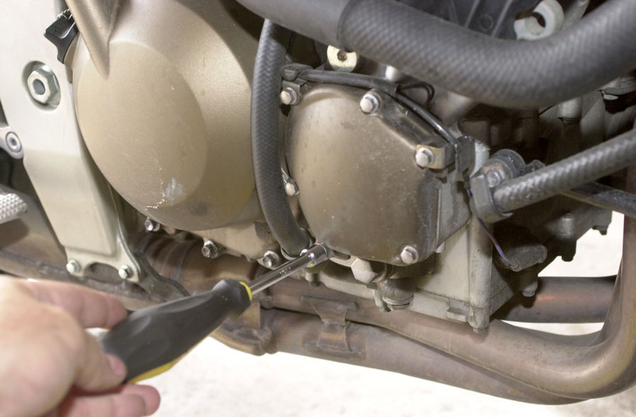
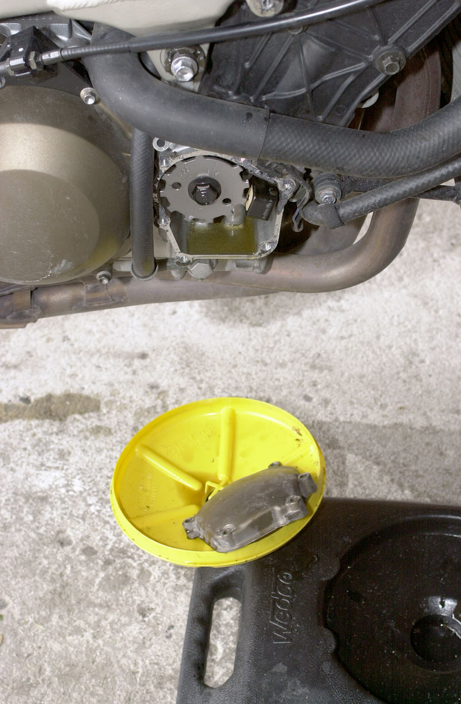
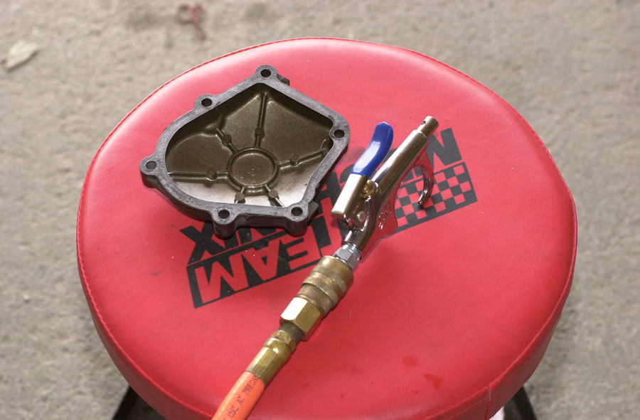
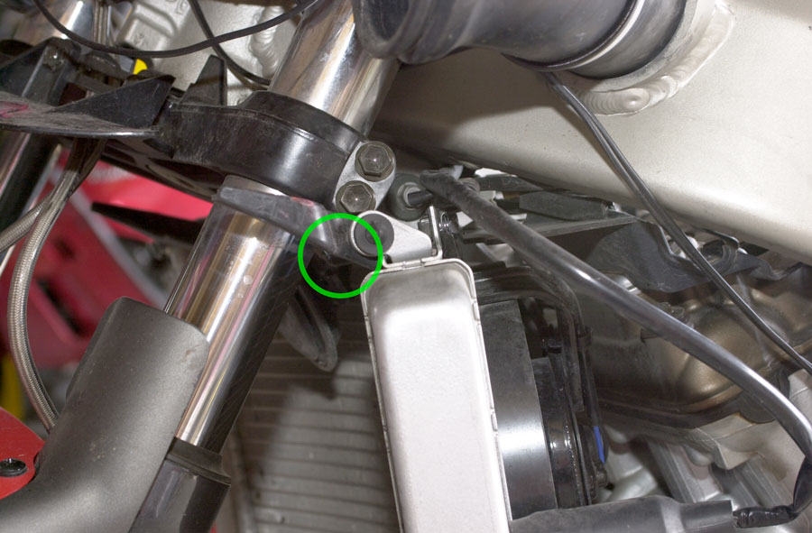
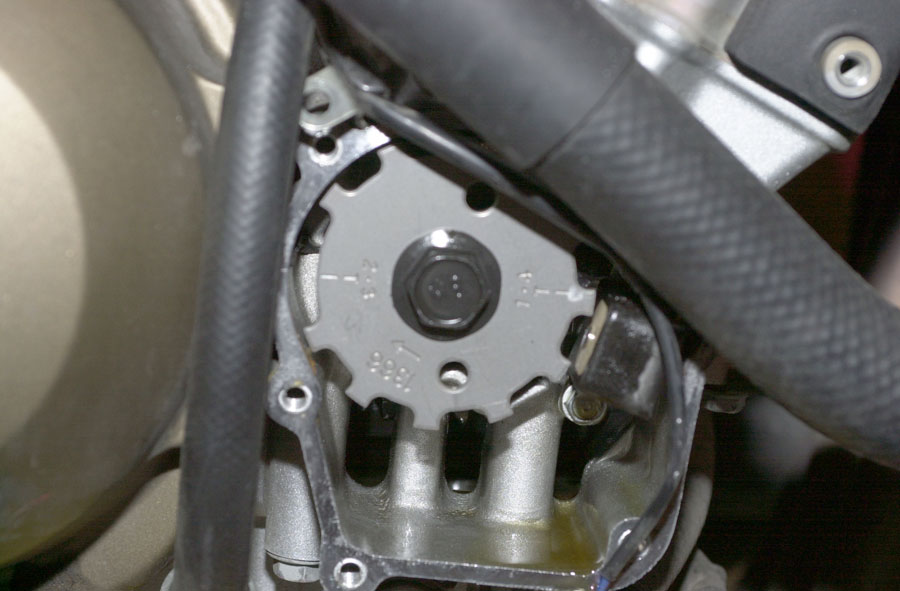
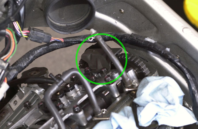
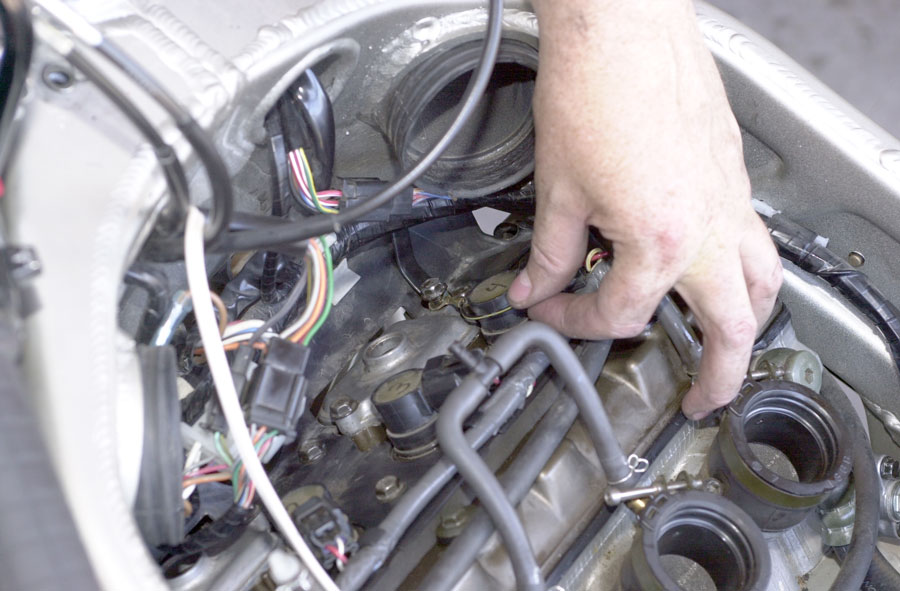
Remove Pickup Coil Cover


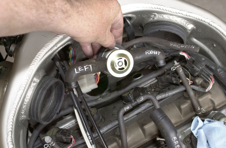
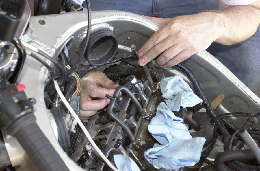
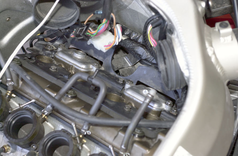
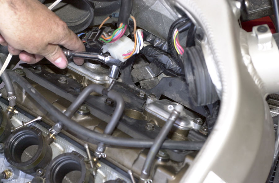
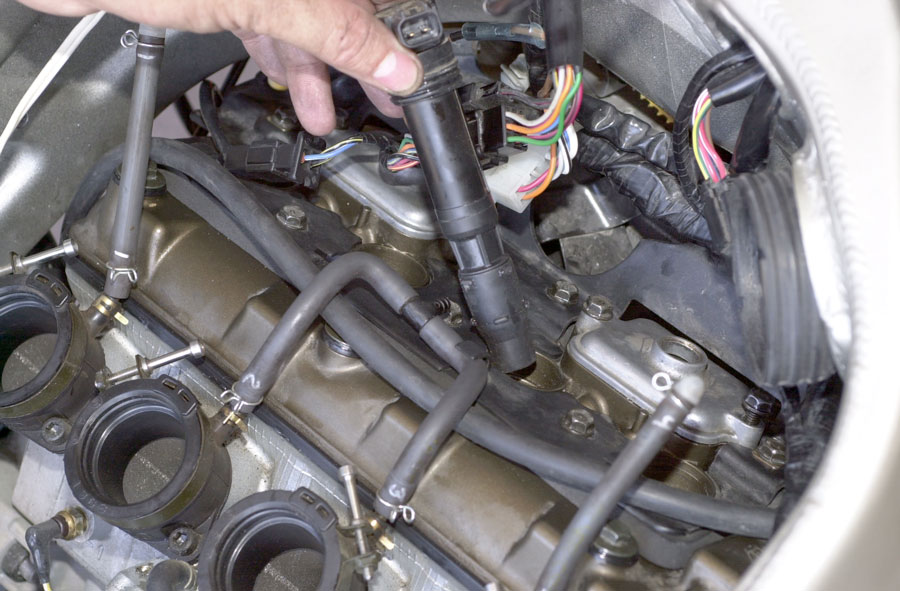
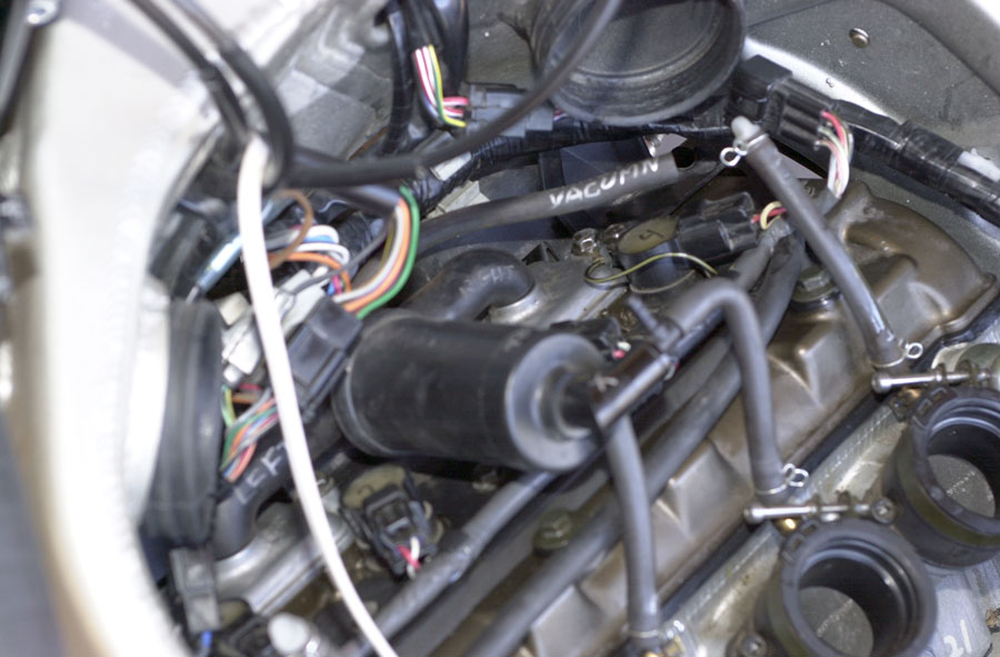
Remove engine top-end connections

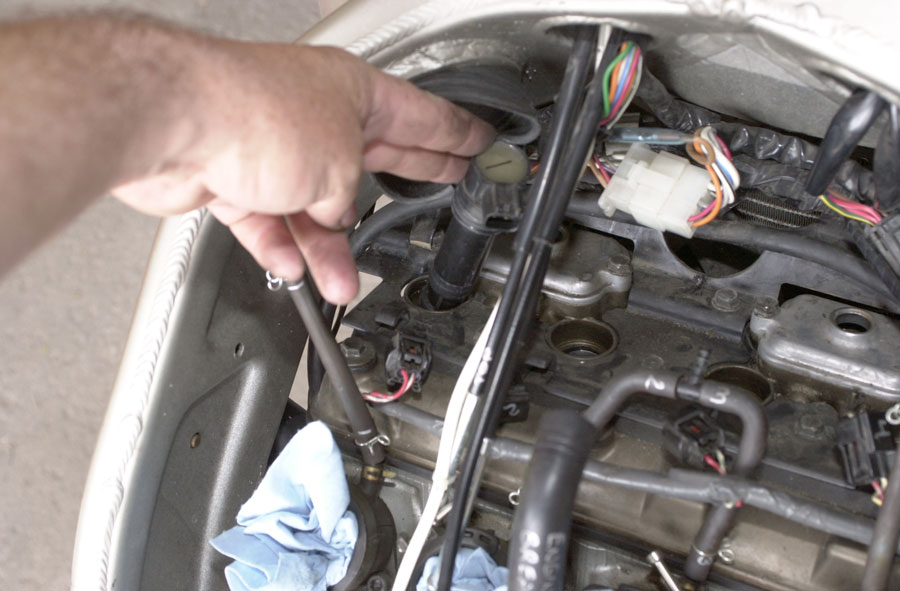


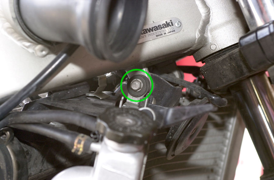
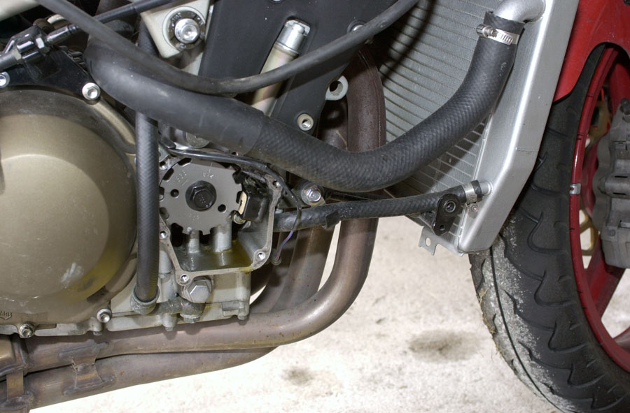
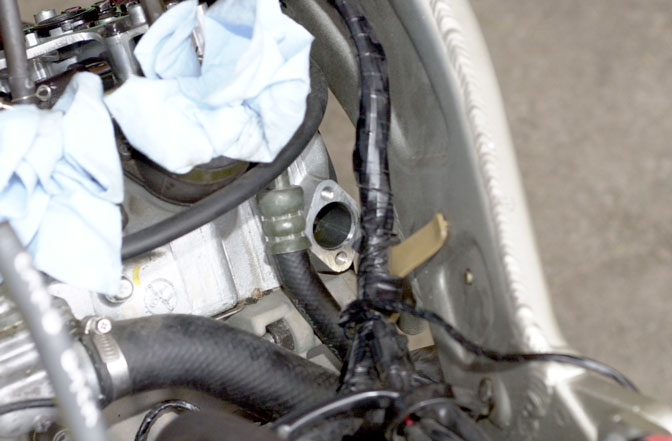
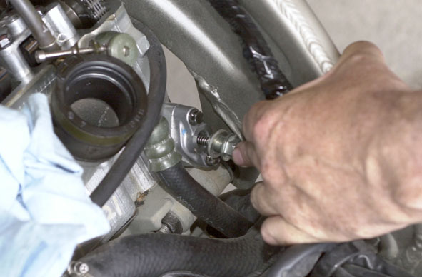
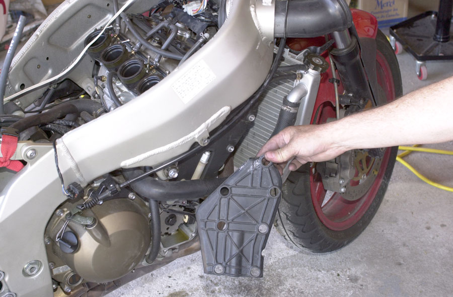
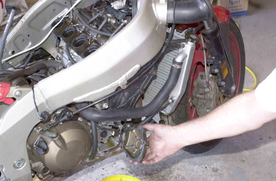
Dismount and Lower Radiator

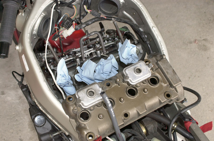
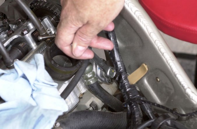
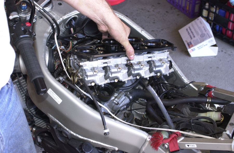
Remove valve cover

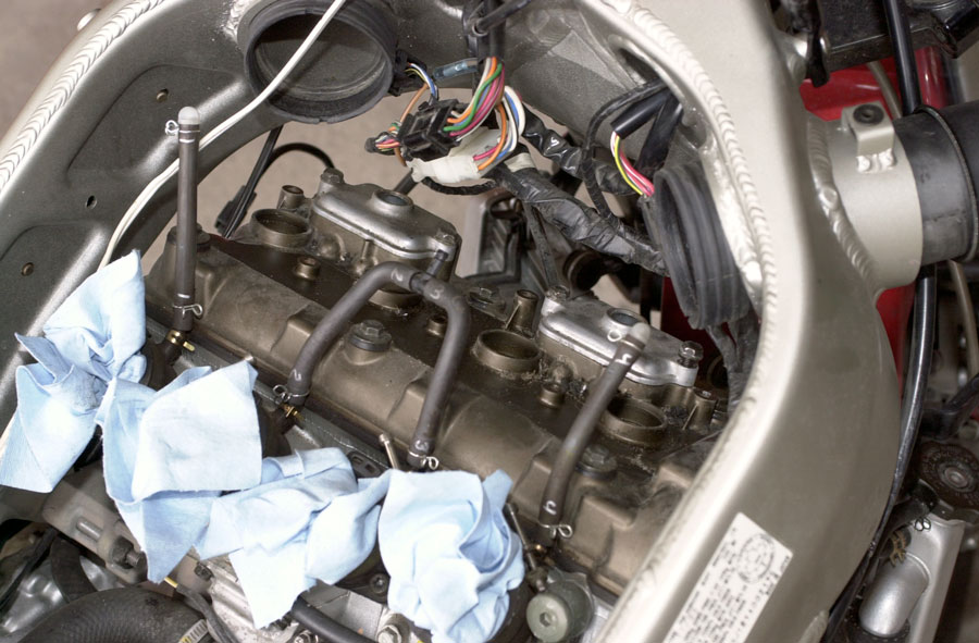
and lift the cover off. It slides out toward the front of the bike, and takes a bit of twisting and turning to get it out.
Actually, it takes a lot of twisting and turning. You will be sure it cannot be removed this way then, suddenly, you will turn it to a slightly different angle and it will lift away like it was never a problem. It’s quite magical.
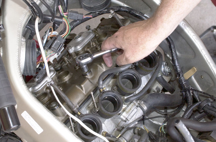
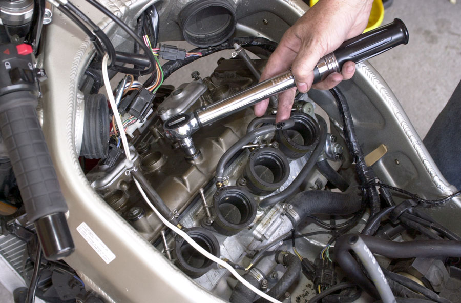
Check Valve Clearances
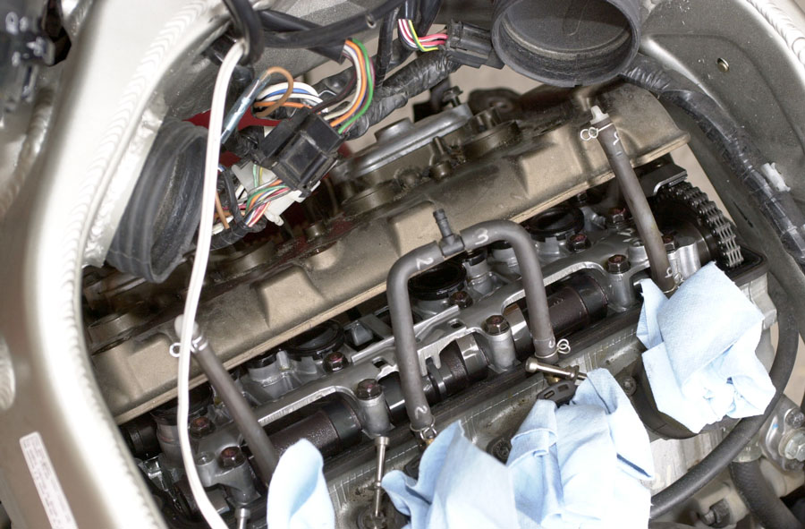
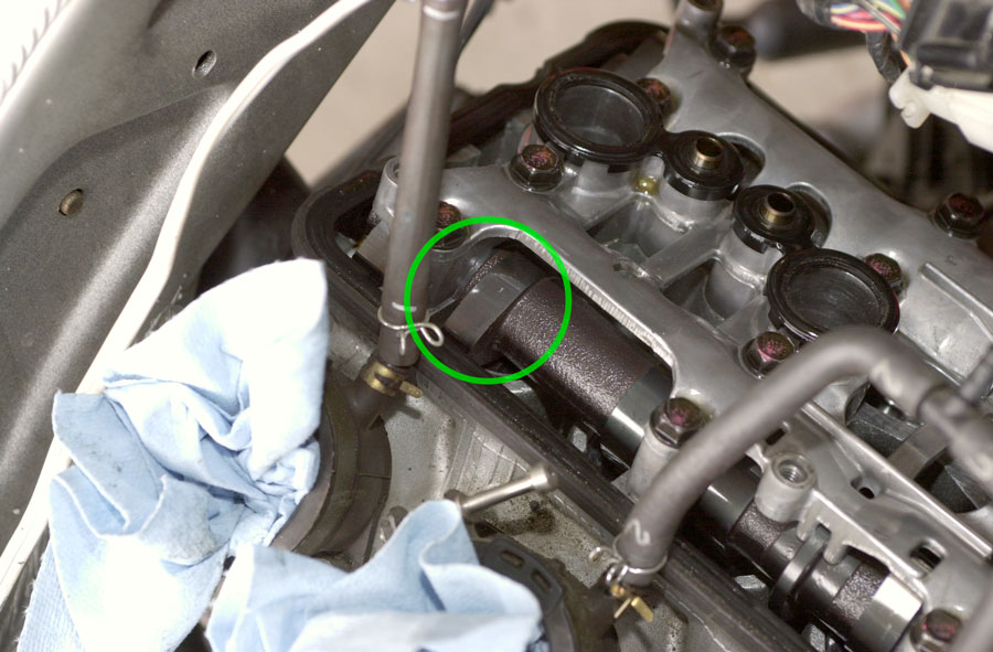
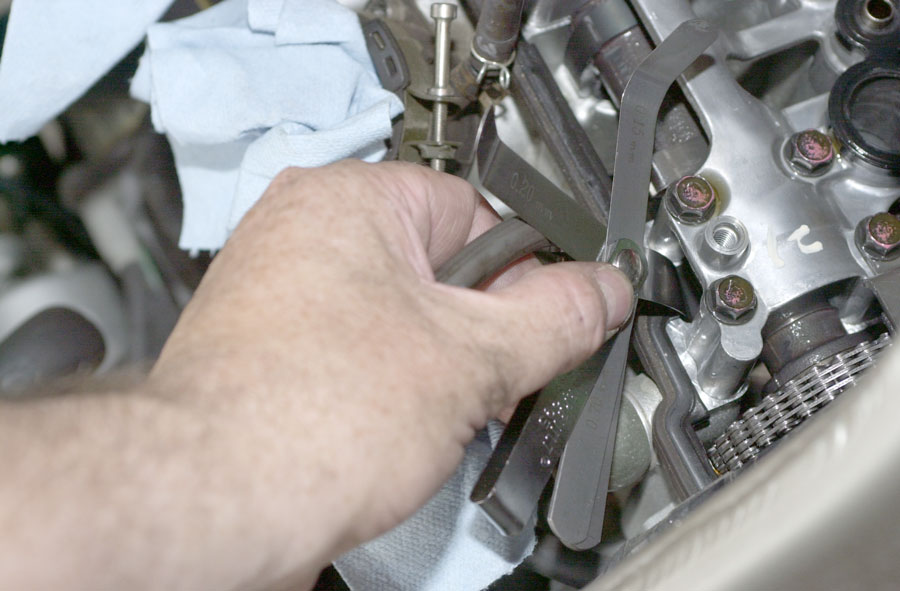
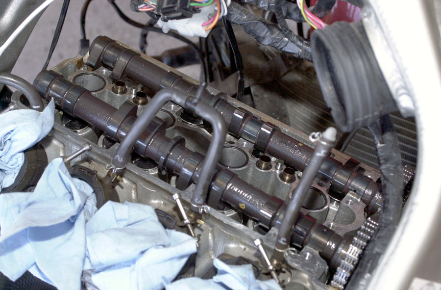
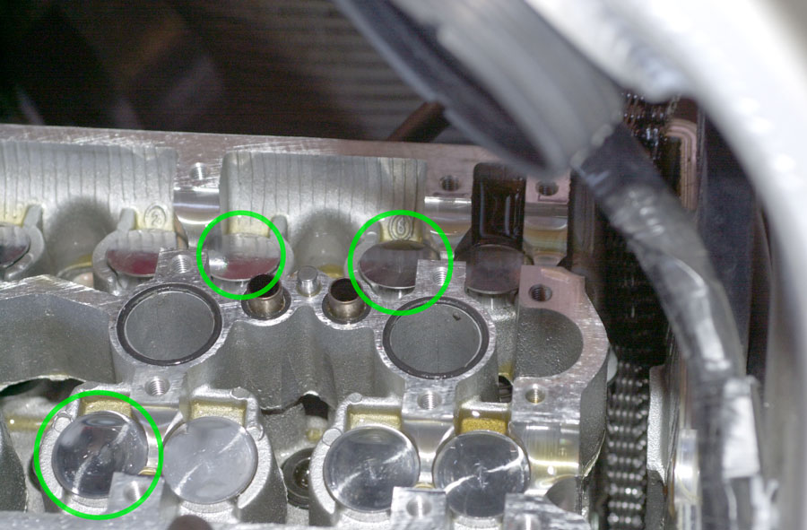
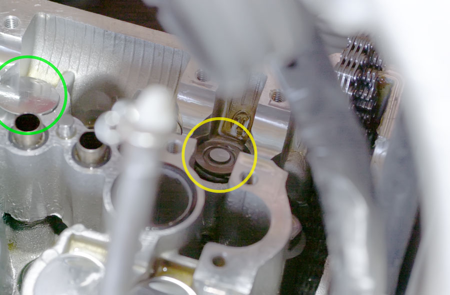
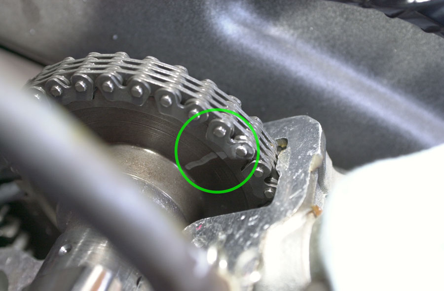
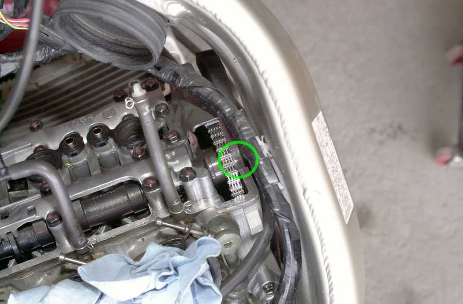
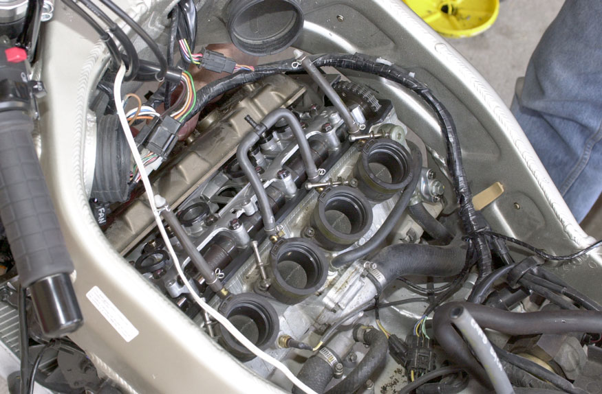
Valve clearances are measured by sliding a measuring feeler under the cam lobes on the camshaft. The bike has 16 such lobes — 4 per cylinder (2 input valves and 2 exhaust valves per cylinder). Here is one of the input lobes (the side set of cams toward the rear of the bike is the inputs).

And, toward the front of the bike, viewed from under the frame, are the exhaust lobes.
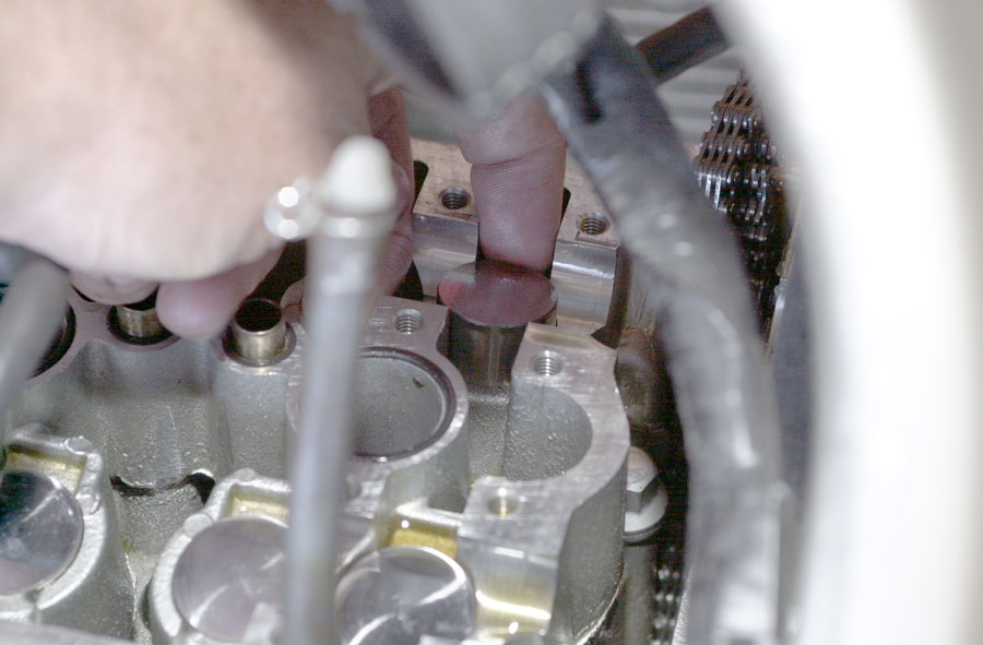
The lobes make contact with, and press down on, highly polished metal cylinders called tappets and these, in turn, press on the valves themselves.


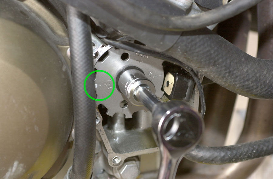
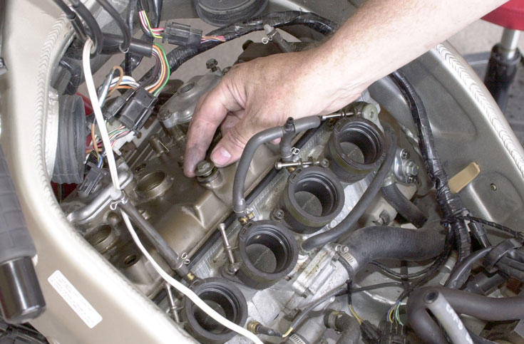
Then, rotate the camshaft to bring the next pair of lobes (2nd from the right here) into position.
The manual suggests an order of checking valves that minimizes the amount of manual rotation. I feel more comfortable doing them in order, so I visually get a set close, then use the registration marks, then repeat on the next set. I tend to work right-to-left since I’m standing on the right side of the bike.

Use the alignment of the registration marks to ensure the positioning is perfect.
Measure all 16 lobes this way.
Keep careful notes: for each cylinder, write down the clearances on both input valves and both output valves. It’s easy to lose track here.
Now What?
If all your clearances are in range, you’re done. If not, you’ll need to adjust them.
My service manual says the input cams should have a clearance of 0.11mm — 0.19 mm and the exhaust cams should have a clearance of 0.22mm — 0.31mm. In the session being photographed here, three of my clearances are not in the appropriate range, so we will adjust the clearances by replacing the shims that set them.
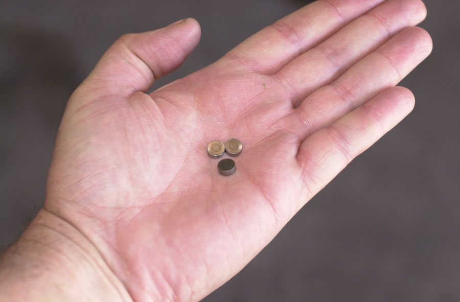
Remove Shims Requiring Adjustment


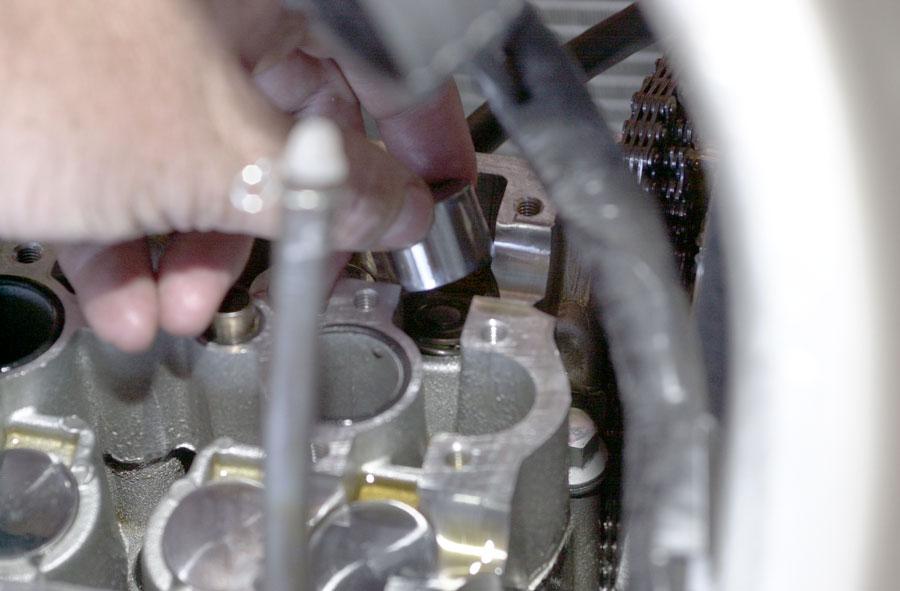

Calculate Sizes and Get Replacement Shims
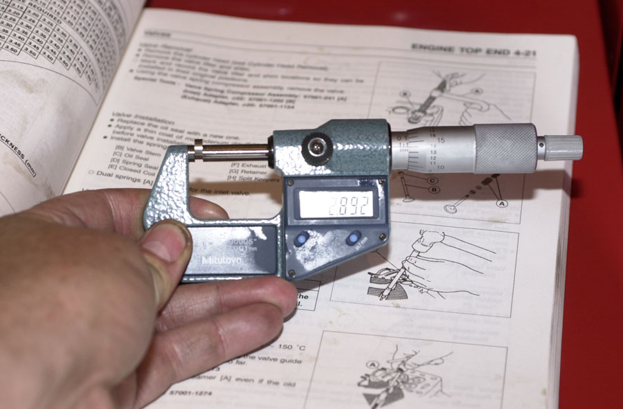
In theory, you can calculate the replacement shim using a table in the service manual and a code stamped on the shim. On my bike, the code is worn by the engine motion and is difficult to read, so I prefer to do the calculation myself. It’s just a question of measuring and subtracting, like this:
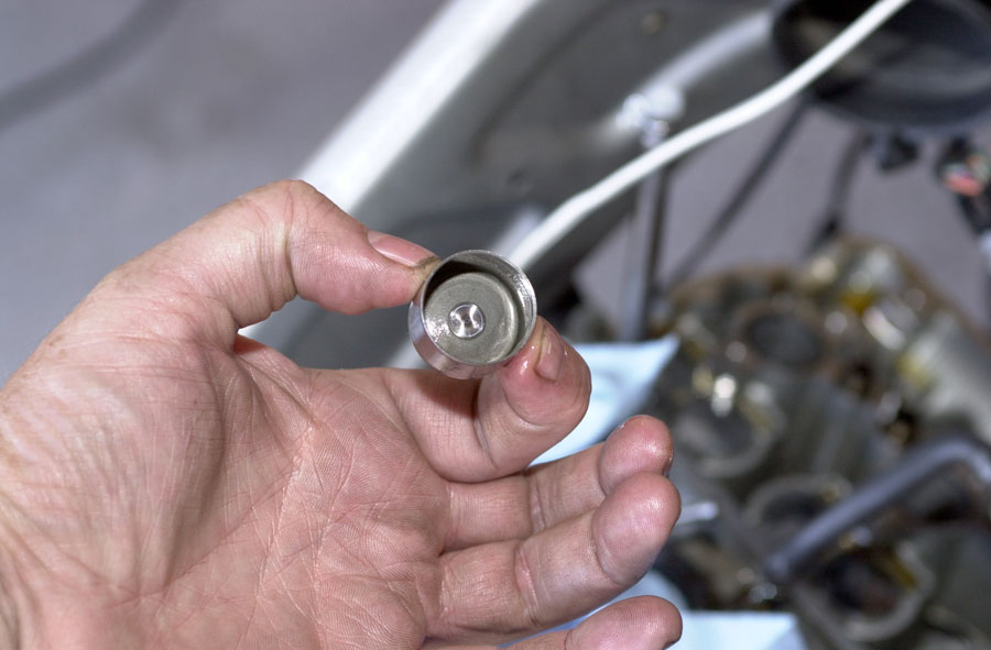
We measure the shim carefully with a metric micrometer. In this case it is 2.892 mm (shims come in .05mm increments, so it was probably 2.90 originally).
This valve’s clearance measured 0.18 mm, but the book says it should be 0.22. So we need the gap to be bigger by 0.22 — 0.18 = 0.04 mm. So we need a shim that is smaller by this amount. 2.892 — 0.04 = 2.852mm, so we’ll need to replace this shim with a 2.85mm shim.


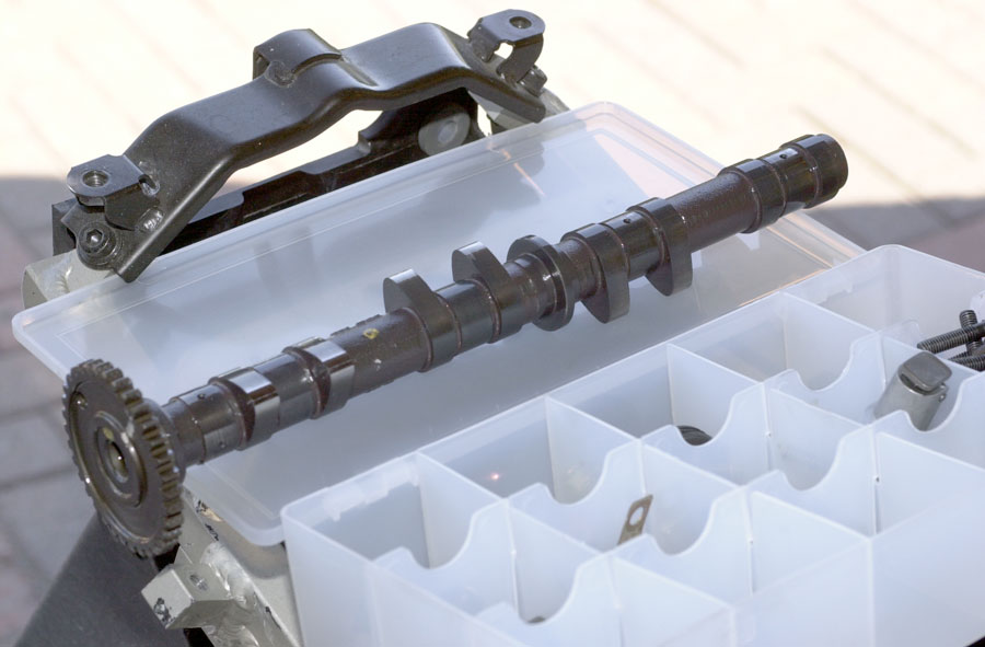
Reinstall Camshafts and Cam Chain
Now you need to re-install the camshafts so you can re-check the clearances.The shafts are marked for “input” and “exhaust” sides — make sure they don’t get mixed.


Making sure the engine is still rotated to “top dead centre” (by checking the pickup coil registration marks), put the exhaust-side camshaft in so the registration marks line up exactly with the surface of the engine housing.
Note: Ensure the chain going down from the exhaust-side camshaft into the engine is tight. i.e. any slack in the chain is on the left, input side, not the right side.
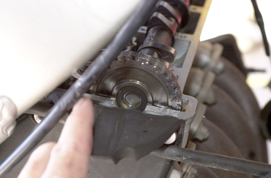

On my engine, one rotates the input-side camshaft so that there are exactly 28 chain rivets between the registration mark on the exhaust camshaft and the registration mark on the input camshaft. i.e. 30 including the rivets at the registration marks. i.e. if you number the rivet at the first registration mark #1, then rivet #30 is at the other registration mark. I pre-marked the rivet with white felt pen to make this easier.


Reset and Reinstall Cam Chain Tensioner


Re-check Valve Clearances

Reinstall Valve Cover
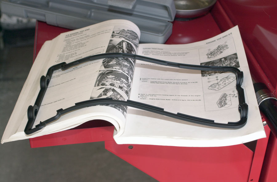
I like to use a new valve cover gasket, although old undamaged ones can be safely reused.
(I had to take the engine apart a second time on another bike when the gasket leaked, so I went through a period where I always used a new gasket; eventually I regained my courage and started carefully re-using old gaskets, with no problem. The leak wasn’t because the gasket was old, it was because I didn’t reinstall it carefully enough.)

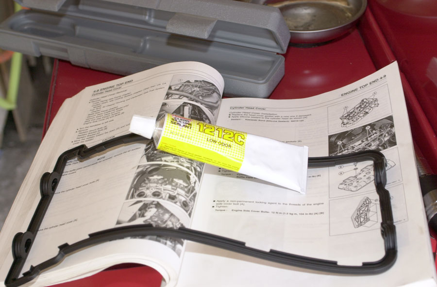
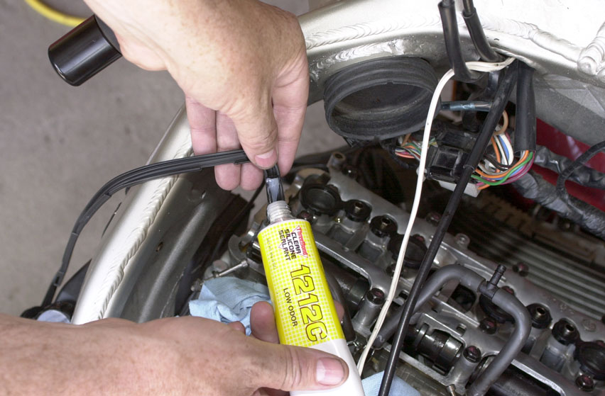
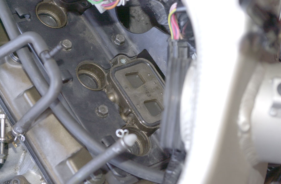
Those recesses are supposed to be sealed with RTV silicone sealant.
(By the way, I’d love to know the purpose of these recesses. The only things I can imagine is either that they create some additional space for rubber to expand or contract when the hot engine changes size, or that they are some kind of “blow out” hole that releases over-pressure during a disaster. But I’m just guessing. Anyone know?)
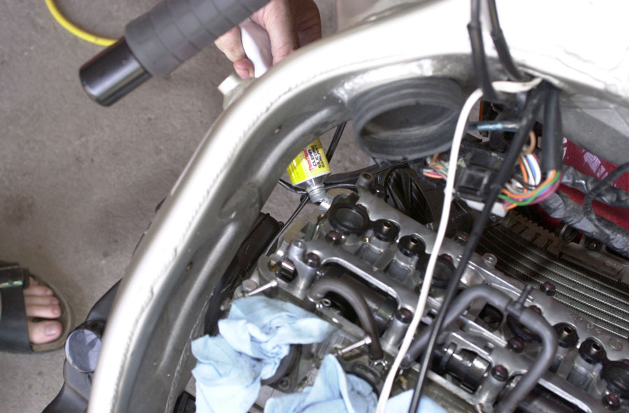


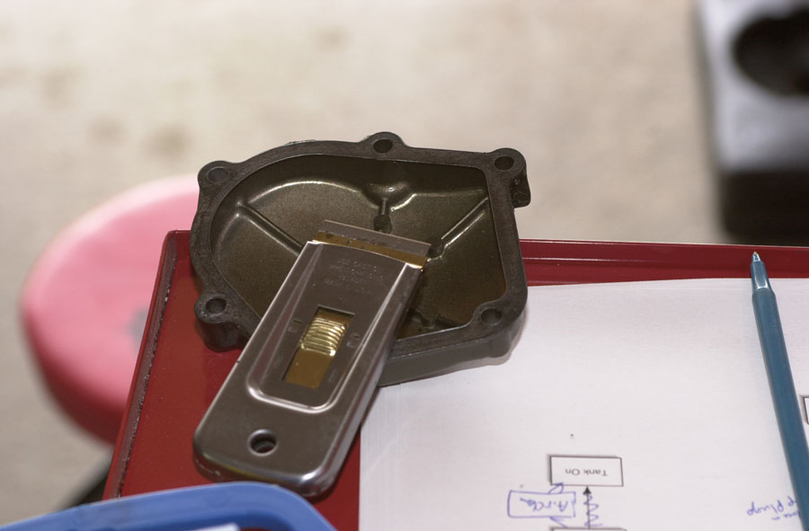
Reinstall Pickup Coil Cover

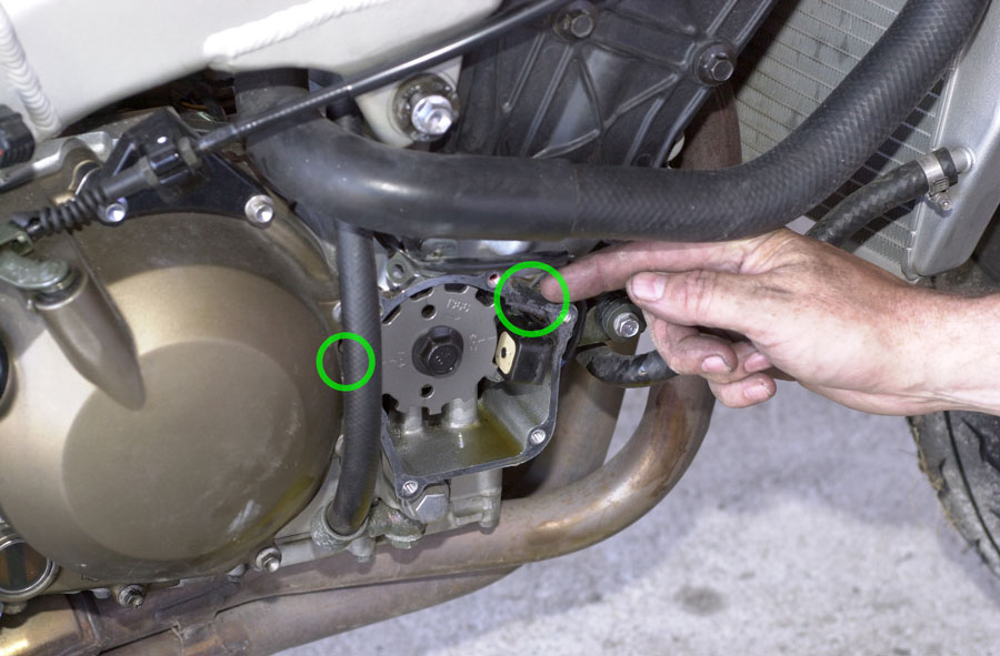
We spread some carefully in the specified spots, being very sure not to get any on the pickup coil mechanism, and re-install the gasket and cover. Again, the torque of the cover bolts is very important, so use a torque wrench. My manual says 11 N-m (95 in-lb). The topmost bolt also calls for LocTite.

Check Air Suction Valves

Reassemble the Rest
Put the spark plug coils back in (this would be a good time to change or inspect the spark plugs if we’re doing a full service).


Replace the radiator, coolant, carburetors, air box, gas tank, and fairings, and we’re done. After putting the carbs back, but before reinstalling the gas tank, would be a good time to balance and synchronize the carburetors.
what is the proper camshaft cap loosening sequence. the kawasaki manual shows a sequence for tightening. what is the sequence for loosening?
salut, j’ai beaucoup appris avec ces explications simples et concrètes, maintenant je suis assez confiant pour faire le travail moi même, sur ma zx600 merci.
im a new bike technician. im currently in school for just this type work. I googled 05 636 valve specs and I found this blog\tutorial and to be honest I learned a lot from it I read it all and will take the job with confidence and my customer will be greatful do u have any honda f4i blogs?
非常有帮助,谢谢!
Can you explain how you kept timing chain in place and cams wgile retightening cam bolts and plate without it akipping teeth?
Ihad to have my buddy help me
Hi , I just checked my 1999 zx6r valve measurements and they are all with in specs, I brought it to this guy and he supposing did them all, BUT now I notice the intake cam is off by 1 tooth, When I have the exhaust gear set at that line for EX the in mark on the intake gear is on pin number 31, now would that make my valves sound like they have a tap, which might really be a ping? Please help, again all valves are within specs, and I have a what sounds like a tap a rap!
Take your time and make sure the marks on the camshafts are as close as possible. It takes a bit of adjusting and prepare to spend several hours. It should be done at TDC, I only have one line on the sproket and if you look down the spark holes, pistons 1 & 4 should be dead top. When the chain tensioner is out, do not try and adjust the timing with a ratchet to shift it slightly. You will mess up the timing and have to take it all apart again. Keep checking marks as you torque.
UPDATE: I had to reset the cam timing marks again and everything was perfect. I followed the torque sequence per the Kawi shop manual and did it in 3 phases (hand tight, 1st torque value roughly 4 inches and 2nd of 8.5 inches. After doing this again I noticed the timing mark on the crankcase shifted. I left it off-mark. I put the chain tensioner in per the manual, tightened it up and cranked the crankcase 2 times to get back to the timing mark again. Perfect. The tensioner will correct the gap. Good luck.
very helpful Thanks.
Hey thanks for the write-up! I thought I’d share something I found… I’ve got a ’96 ZX-6R, and just finished doing my valves for the first time since owning the bike. My Clymer manual has the math wrong, it’s saying that as the valve recesses, you need a larger shim. It even has an example where they start with a smaller shim, the feeler blade gap was under spec, so they installed an even bigger shim. I thought that just didn’t make any sense so I Googled it and came across this post. Thank you sir!
Sometimes you do need thicker shims as the valve stem shortens under cyclical compressive shock loads – normal operaton.
You’re the man!
Thanks a bunch- (My bike thanks you too)
THE RECEESES IN THE CYL. HEAD AT THE END OF THE CAM SHAFT ARE FOR LINE BORING THE HEAD AND THE CAM PLATE I.E. MACHINING PROCESSES.
Nice Tutorial!
One detail I need to know is the correct sequence for tightening the cam cap bolts. Nothing in my shop manual specifies any tightening sequence.
Cheers!
too complicated for me lol but excellent posts man keep em coming!
Well take a look at how the camshafts sit in the head. Next we have the cam tower. These parts are match machined heas one when torqued in place (this is why torque values are important)
Those “recesses” allow the cam journal to be machined and honed. You cannot just swap these parts from motor to motor as each one will be different. IF you break the tower you will need a new head. Make sure you snug them up very slowly and in the correct sequence&|60;:)
First time I’ve attempted a job like this on my Ninja and thanks to your post its all gone really smoothly. Brilliant job – many thanks
Thank you so much!
hello.
I have had my valve clearances done, 8 needed doing. carbs balanced, and still my engine is making that (diesel) noise, hot or cold. So now Ive got a tensioner (not ape) O.E one. After looking at your piece above, I feel very confident about doing my manual cct, as all other work has been done by my local dealer who says my cct is the last thing you check after the other work??????
A big thank you for the time and effort you put into this.
Cheers.
brilliant post. cheers.
key points for this procedure again inch pounds on the torque wrench read the markings carefully.
And when using the feeler gauges and micrometer the touch is very key. You want there to be slight drag, not so much you cant get the feeler in or can’t pull it out without dugging but not so loose it just slides free you want just the right amount of resistance
And when you all re-shimed and have the cams back on using the bolt spin the engine all the way around 2 or 3 times before recheckin the tolerance
Thanks for the painstaking job of photographing all of your steps. I have a 94 ZX6 that I plan on adjusting. I’m contemplating waiting until the end of the season, but not knowing if it’s ever been checked by previous owners, I not sure if I should wait.